
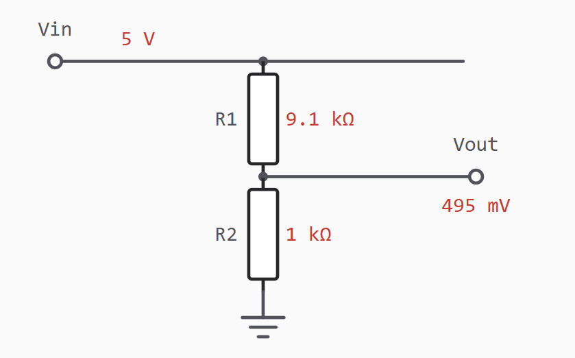
Voltage divider calculator notes: the three hurdles beyond Vout = Vin·R2/(R1+R2)
Tool URL: https://www.dd-cat.cn/tools/voltage-divider
A voltage divider is probably the first circuit every hardware engineer learns: two resistors in series, Vout = Vin × R2/(R1+R2) — elementary arithmetic. But when it's time to draw the schematic and place the BOM, that formula only answers a third of the question. The remaining two-thirds: is that resistance value actually available to buy? Will the resistors get hot? What happens when the next stage loads it?
When building the online tools for dd-cat.cn, the voltage divider calculator — the first of the five in the resistor family — was an obvious one to have. But it's more than just a calculator: we built those beyond-the-formula concerns into the default workflow. Let's walk through them in this article.
Hurdle one: the calculated resistance isn't on the shelf
Hand-calculating a 0.5V output from 5V, the easiest answer is R1 = 9k, R2 = 1k. Unfortunately, there's no 9k in the E24 series — 9.1k exists, 8.2k exists, but 9k doesn't. Standard resistance values aren't continuous: IEC 60063 divides each decade into 12 steps (E12), 24 steps (E24), or 96 steps (E96), and real-world resistors can only be chosen from those steps.
Many calculators skip this step and just hand you a 9k. This tool works differently: after you enter the raw values, it first rounds them to the nearest standard value in the series you've selected, then computes with the rounded values. In the default example, R1 rounds from 9k to 9.1k, the output changes from 500mV to 495mV, and the results area includes a dedicated line: "Rounding deviation −0.99%".
What does −0.99% mean in practice? On a 12-bit ADC powered at 3.3V, 4.95mV is roughly 6 counts. For a battery level indicator, no big deal; for a calibration reference, you'll want to think twice — that's when you switch the series to E96, and 9.09k is waiting for you in the table.
The series dropdown goes from E3 all the way to E192, corresponding to tolerance grades from ±20% down to ±0.5%; if you want to see ideal values first, pick "No rounding".
Hurdle two: the divider branch is leaking power
A divider network is a permanent path from supply to ground, with current I = Vin/(R1+R2) flowing continuously. The tool lists this current and the power dissipation of each resistor in the results (default example: 495µA, R1 about 2.2mW, R2 about 0.25mW).
Dividers in signal chains run at milliwatt levels — even an 0402 can handle it, so heat is a non-issue. What you really need to watch is battery-powered scenarios: a 100k + 100k divider across a 3.7V lithium cell to measure battery voltage draws 18.5µA, which seems small, but over a year that's 162mAh — and a CR2032's nominal capacity is only about 220mAh. So in low-power designs, keep the total resistance as large as possible.
But the total resistance can't be infinitely large either — which brings us to the third hurdle.
Hurdle three: the formula assumes no load
The output isn't floating. The next stage's input impedance is in parallel with R2, the equivalent resistance shrinks, and Vout drops. The rough engineering rule of thumb is that the next stage's input impedance should be ≥ 10×R2, which keeps the loading error under 10%; if you want to be precise, parallel the stage impedance with R2 and recalculate. The tool's results area explicitly labels Vout as the "no-load value" — a reminder of exactly this.
An ADC sampling input adds another layer: the input isn't purely high impedance, the sample-and-hold capacitor must fully charge within the sampling window, and if R1+R2 is too large it won't charge in time. Tens of kΩ is a common compromise — and that rule-of-thumb value is written directly into the tool's notes.
Handy safeguards
Vout larger than Vin? You probably swapped R1/R2 — the page warns you directly;
Resistance outside the 100Ω–1MΩ standard table range gets rounded to the endpoint values, and you're told about it.
Change an input and the resistance and voltage labels on the diagram to the right update with it — no need to mentally reconstruct the wiring.
Sharing is a link
All calculations go through GET parameters, so the URL after computing already carries every input. Send
https://www.dd-cat.cn/tools/voltage-divider?vin=12&r1=30000&r2=10000&series=E24
to a colleague, and they'll open exactly your 12V→3V configuration with full results — no screenshots or value-matching needed. The page is server-rendered, so even with JavaScript disabled in the browser, the full results still appear.
What it doesn't do
Single stage, no load, steady state — beyond those three (loaded precision analysis, temperature drift, transients), it steps aside; that's a simulator's job. It solves only one problem: before you order resistors, it straightens out the gap between "calculated" and "available to buy".
The resistor family on the site also includes series/parallel equivalent, color code reader, RC cutoff frequency, and LC resonance — four more tools with the same idea: the formulas are simple, but the "what's next" engineering steps are built into the default workflow. Come try them.