
This is a spin-off of the "Black Box Castle" series. The three main chapters covered Thévenin's theorem, Norton's theorem, and Kirchhoff's two iron laws: folding a network into two elements and turning loops into equations. This installment lays the third foundation stone — when a circuit has several sources, how to solve it one source at a time.
Many people trying to solve a multi-source circuit by hand crash the moment they write out a system of equations: three equations, three unknowns, and one sign error loses the whole game. The superposition theorem splits "all sources at once" into "one source at a time" — each pass leaves only one source, and the circuit immediately collapses into series and parallel. It isn't hard; what's hard are three details: how to "turn off" a source, how to carry direction signs, and what it cannot superpose.
The Story: Two Water Sources, One Water Bucket
Ali needs to fix the water supply for the mill. Water comes from three places:
- A water tower on the hill: the water level difference is fixed at 12 feet — no matter how much flows out, the head stays the same. This is a constant-level source (voltage source);
- An artesian spring on the cliff: it always gushes 3 buckets per hour, and keeps gushing no matter how high the downstream water level rises. This is a constant-flow source (current source);
- The pond at the foot of the hill is the destination of all water, and the reference plane for measuring water level (0 V).
The tower's water flows through a 2 Ω bamboo pipe into bucket A at the head of the channel; the spring feeds water directly into the bucket from below; there is a 6 Ω leak hole in the side wall back to the pond; and a 3 Ω main channel beside the bucket also returns to the pond.
The miller asks: "With all three water sources on together, how high is the water level in the bucket? How much flows through each pipe?"
Grandpa Copper-Nail says: "You don't have to solve all three at once. First plug the spring, turn on only the tower, and take a reading; then remove the tower and replace it with an open pipe (level drops to zero), let only the spring flow, and take another reading. Add the two readings together, and that's the answer for all three running together."
Ali: "Why can they be added?"
Grandpa: "Because the channel is linear — pour in twice as much water, and every water level and flow rate exactly doubles; with two sources feeding together, the result at every point is the sum of what each would do alone. The water doesn't 'negotiate' with itself, and it won't produce any new tricks by cancellation."
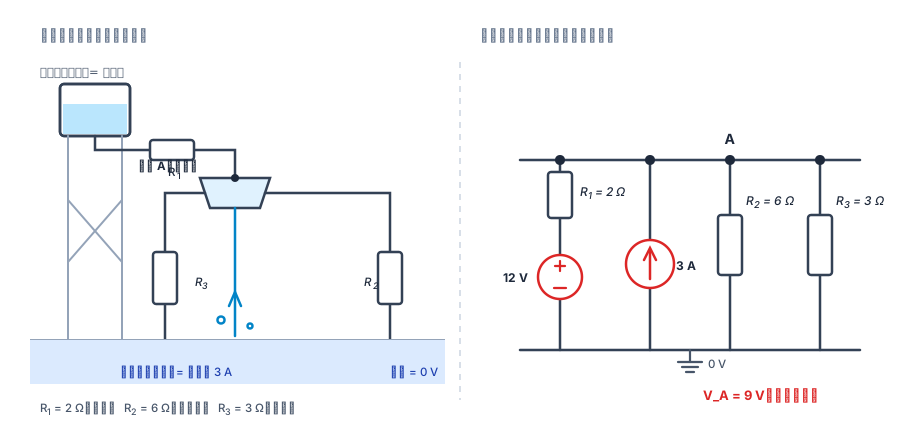
Figure 1: The tower's "constant level" makes it a voltage source, the spring's "constant flow" makes it a current source, the bamboo pipe and channel are resistances, and the pond is the 0 V reference. Three kinds of things hang on the same bucket (node A) — this is exactly the circuit we'll split up later.
The Theorem: Total Response = Algebraic Sum of Each Independent Source's Solo Response
is the current in any branch, or the voltage between any two points; is the value of that same quantity when only the -th independent source is active and all other independent sources are zeroed out.
Written more like a "transfer function":
and are determined solely by the resistor network (units are V/V and V/A, respectively), completely independent of how large the sources are. This is what linear means: double a source, and its contribution doubles; reverse a source, and its contribution flips sign.
Why does it always hold? Nodal analysis makes it clearest. The node equations of a linear circuit are a system of linear algebraic equations:
where is the right-hand-side term contributed by the -th independent source alone (current sources enter the right-hand side directly, and voltage sources enter after equivalent transformation). Therefore
Because the equations are linear, the solution is necessarily the superposition of the individual solutions from each excitation. The theorem is not an "approximation" or a "trick" — it is simply a property of linear equation systems.
There is only one prerequisite: the circuit must be linear. Resistors, inductors, capacitors, mutual inductance, ideal transformers, and controlled (dependent) sources are all linear elements; diodes, Zener diodes, saturating inductors, and a lit incandescent filament are not.
The Extinguish Method: The Correct Way to "Turn Off" a Source
The most error-prone part of superposition isn't writing equations — it's "how to turn off a source".
| Element | Becomes after zeroing | In one sentence |
|---|---|---|
| Ideal voltage source | Short circuit (0 V wire) | Level to zero = an open pipe, not a blocked channel |
| Ideal current source | Open circuit (0 A break) | No flow = plug the spring, not a shorting pipe |
| Real voltage source ( in series with ) | Short only , keep | Tower removed, pipe still there |
| Real current source ( in parallel with ) | Open only , keep | Spring plugged, leaking channel wall remains |
| Controlled source | Keep as-is, never touch | It's not a water source, it's a "servo sluice gate" |
The last row is the key point, explained separately below.
One more point that's easy to confuse: "zeroing" is not "turning off a switch." In a real circuit, pulling out a battery leaves the branch open (open circuit), not 0 V. In analysis, "zeroing a voltage source" means replacing it with an ideal wire — a mathematical equivalence, not a physical operation. For the same reason, never actually short a power source with a wire in engineering practice.
The Trial: 12 V Tower + 3 A Spring
For the circuit on the right in Figure 1, solve it first with superposition, then verify by writing KCL directly.
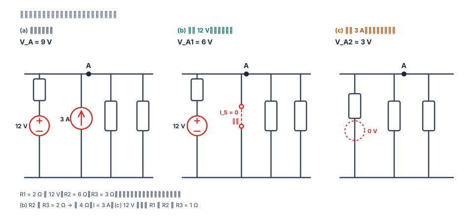
Figure 2: In all three diagrams, the resistances and reference directions must not change — only the sources change: zeroing the current source means opening it (b), zeroing the voltage source means shorting it (c).
Subcircuit One: Only the 12 V Tower On (Spring Plugged)
The current source is open, so that branch disappears entirely. The remaining 6 Ω (leak hole) and 3 Ω (main channel) are in parallel, in series with the 2 Ω bamboo pipe:
Three branches: enters the bucket through the bamboo pipe, the leak hole carries , and the main channel carries .
Subcircuit Two: Only the 3 A Spring On (Tower Replaced by an Open Pipe)
The voltage source is shorted, the 2 Ω bamboo pipe is connected directly to the pond, so the 2 Ω, 6 Ω, and 3 Ω paths are all in parallel:
Now the water in the bamboo pipe flows from the bucket back to the pond (opposite to the "into the bucket" direction assumed above, so it is recorded as ): ; leak hole ; main channel .
Add Them Up and Reconcile
| Quantity | Only on | Only on | Superposed result | Direct KCL check |
|---|---|---|---|---|
| (up positive) | ||||
| (down positive) | ||||
| (down positive) |
Direct verification: KCL at node A says "inflow = outflow,"
While we're at it, do a power reconciliation (as in the previous article, this step catches most sign errors):
| Element | Power |
|---|---|
| 12 V voltage source | Supplies |
| 3 A current source | Supplies |
| Dissipates | |
| Dissipates | |
| Dissipates |
, and it all goes to — to the penny.
One Iron Rule: Power Cannot Be Superposed
The actual power on is:
But adding the powers calculated from the two subcircuits separately gives only:
A full 12 W short. The gap hides in the expansion:
That last cross term is exactly the part that exists only when both sources act simultaneously — it belongs to neither source. Voltage and current are first-order quantities (linear); power is a second-order quantity (a product); the superposition theorem holds only for first-order quantities.
The correct order is always: superpose voltage and current first → then compute power from the superposed values. Doing it the other way around is always wrong, and it's a very "plausible" mistake — looking only at that 15 W, you'd never discover you're missing 12 W.
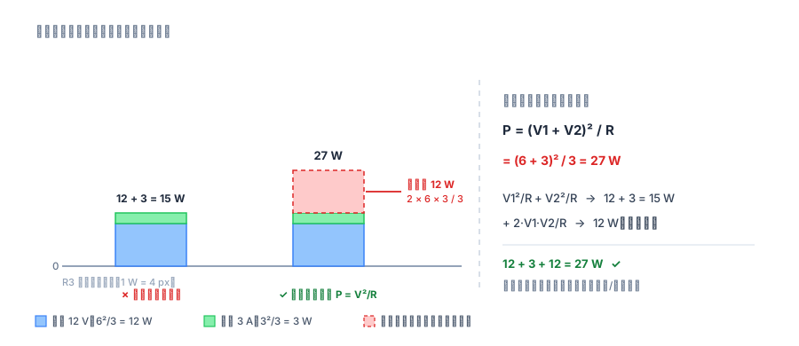
Figure 3: That red 12 W exists only when both sources work simultaneously. It is neither the contribution of "only 12 V on" nor of "only 3 A on," so it cannot be split.
Controlled Sources: The Only Source You Cannot "Turn Off"
Independent and controlled sources look alike but have completely different roles:
- Independent sources are "excitations": their values are self-determined; they can act alone and can be zeroed;
- Controlled sources are "elements": their values are determined by a voltage or current elsewhere in the circuit (, ); they do not produce energy themselves.
Therefore, in a subcircuit, controlled sources must be kept exactly as they are. If you "turn off" a controlled source too, the control relationship breaks, and that subcircuit is no longer part of the original circuit — the numbers you compute are meaningless.
Corollary: the number of subcircuits = the number of independent sources, independent of controlled sources. A circuit with 2 independent sources and 3 controlled sources splits 2 times, not 5.
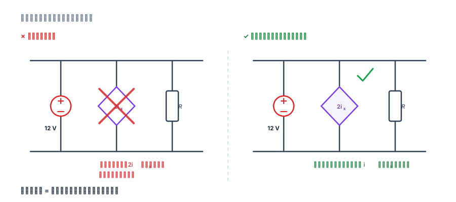
Figure 4: A controlled source is like a servo sluice gate — how wide the gate opens is decided by the water level elsewhere. Tear out the gate, and you've deleted that "decision" as well.
Five Points to Remember
- Valid only for linear circuits. Circuits containing diodes, Zener diodes, magnetic saturation, or incandescent filaments cannot use it directly; only after small-signal linearization around the operating point can superposition be applied to the "small signal."
- Fix directions first, and keep them consistent throughout. What you superpose are algebraic quantities — carry the minus signs from each subcircuit into the sum. Changing reference direction midway is the most common error in this kind of problem.
- Don't superpose power, or any second-order quantity. Power, energy, and RMS values at different frequencies cannot be added directly.
- Don't turn off the internal resistance of real sources. You turn off the "ideal source"; the internal resistance is a real, physical element.
- Controlled sources cannot be zeroed. The number of subcircuits equals the number of independent sources, not .
One more piece of "good news": the superposition theorem holds for arbitrary waveforms — DC, sinusoids (phasor method), square waves, and transients in the Laplace domain all work. It depends only on the circuit's linearity, not on what the signal looks like. In dynamic circuits, "zero-input response + zero-state response = total response" is also superposition at its core.
Superposition, Thévenin, and Norton Are the Same Linearity
Three things that look different are actually three uses of the same property:
| Theorem | What it splits | Where it's used |
|---|---|---|
| Superposition | Split by excitation | Hand-solving multi-source circuits, and answering "how much did each source contribute" |
| Thévenin / Norton | Fold by port | Equivalent simplification when only the external load matters |
| Extinguish method for | Zero the independent sources | Exactly the same zeroing action as superposition |
Precisely because it's the same linearity, the three theorems share the same boundary: nonlinear elements, second-order quantities like power, and devices beyond the model's range — none apply.
Small Exercises for Yourself
- Change the spring from 3 A to 2 A and recompute and the three branch currents. (Hint: with only the spring on, ; answers: , , , )
- Reverse the 12 V tower (+ pointing down) and recalculate. Observe: only the "only on" subcircuit changes sign; the spring's path doesn't budge.
- A circuit has 4 independent sources and 2 controlled sources. How many subcircuits does superposition require? If two of the voltage sources are in series and can be merged into one, how many fewer splits?
The Tail
One sentence is enough to remember: turn on one source at a time, compute, then add with signs; calculate power last. As for how to "turn off" sources — short voltage sources, open current sources, keep internal resistances, and never touch controlled sources — memorize these four, and the rest is just arithmetic.
Other posts in the series: Thévenin's Theorem · Norton's Theorem · Kirchhoff's Laws · MOSFET Parameters Quick Reference