
This is the third installment of the "Black-Box Castle" series: the first two covered how to collapse a complex network into just two components (Thévenin's theorem, Norton's theorem); this one goes back to an even more fundamental layer — the two iron laws no circuit can escape: Kirchhoff's Current Law (KCL) and Kirchhoff's Voltage Law (KVL).
The formulas contain only a couple of symbols, and many people can recite them flawlessly, yet the moment they do a hand calculation something goes wrong: arrows labeled backwards, supply rises and drops mixed up, loop direction switched midway, and the final numbers don't match. The problem has never been the formulas — it's the sign conventions and the boundaries of the knowledge. This article clarifies both once and for all.
The Story: The Forest's Water Channels
Ari the little fox isn't fetching water this time; he's building a network of water channels for three households in the forest: water is drawn from the castle and distributed to the three homes along the way. The channel network has splitter posts, loops, and elevation changes.
Grandpa Copper Nail says: laying the channels only requires obeying two iron laws; everything after that is just arithmetic.
Iron Law #1 (KCL): At a Splitter Post, What Flows In Must Flow Out
Water can't appear out of nowhere or vanish into nowhere. So at any splitter post (a node in the circuit), the water flowing in must equal the water flowing out:
Or, more plainly:
Two points are the easiest for beginners to get fuzzy on:
- A "node" is an entire piece of conductor, not just a dot on paper. The whole copper pour connected by a wire, an entire ground plane — all count as one and the same node (a so-called generalized node). When a schematic draws several ground symbols, physically they're the same post.
- Current must have a direction before you can write an equation. The direction is the reference direction we ourselves assume — pick anything first; a negative result simply means the actual direction is opposite to your assumption. The physics is perfectly fine.
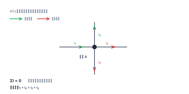
Figure 1: Green arrows = assumed inflow, red arrows = assumed outflow. However much flows out, that's how much must flow in; when written as the algebraic sum , as long as the entire article consistently takes "inflow as positive", the signs won't get scrambled.
Iron Law #2 (KVL): Walk a Full Loop Back to the Start, and the Water Level Must Return
Walking around any closed water route, you'll climb and you'll descend, but when you return to the starting point, the elevation is necessarily the elevation you started with: the total rise equals the total fall:
To actually keep the books, just watch two things:
- Power sources: walking from "−" to "+" is a rise (+U); walking the other way is a fall (−U);
- Resistors: crossing a resistor in the direction of current is a fall (−IR); crossing against the current is a rise (+IR).
A one-line mnemonic: downhill with the water, uphill against it.
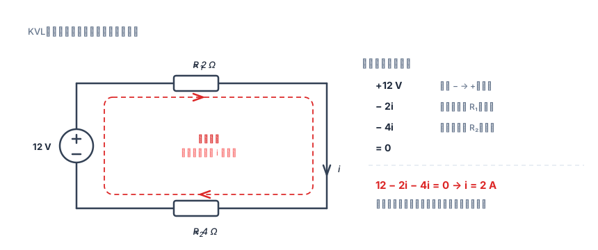
Figure 2: Walk clockwise around the red dashed line once and write down every potential change: the source rises , the two resistors each fall and ; returning to the start must bring the total to zero, so .
KVL has another often-overlooked strength: it holds for any closed path, not just "meshes". You can go around a big loop, a small loop, or even a figure "8" — as long as it's closed, the algebraic sum is zero.
The Two Iron Laws Together Can Solve Any Circuit
For a connected network with branches and nodes, the total number of independent equations is exactly :
| Law | Number of independent equations | Where it applies |
|---|---|---|
| KCL | Nodes (including generalized nodes) | |
| KVL | Loops (meshes) |
Why is KCL one short? Because the currents flowing into all nodes necessarily sum to 0 — the last node's equation is a linear combination of all the previous ones, so writing it down is pointless. Likewise, for KVL writing just the "meshes" is enough; if you also write every larger loop you'll pile up a bunch of dependent equations that you can't solve cleanly and that are easy to get wrong.
The Trial: 12 V and 6 V Fight Over One Node
Three branches hang off node A, all connected down to node B below (take ):
- Left branch: a source (+ up) in series with ;
- Middle branch: ;
- Right branch: a source (+ up) in series with .
All three currents are assumed to flow from B to A (upward). Write the equations under that assumption:
KCL at node A (all three branches point up, i.e., all flow into A):
KVL for the left loop (clockwise: start at B, go up through the source, right through , down through , back to B):
Note the third term: is assumed upward, and we pass downward through — against the current — so it's a rise, taken as .
KVL for the right loop (clockwise: up through , right along the top, down through and the 6 V source, left back to B):
Item-by-item bookkeeping: this time is traversed upward with , a fall of ; is traversed downward against , a rise of ; the 6 V source goes from "+" to "−", a fall of .
Solving the three equations together (just substitute and from the last two into the first):
The node voltage comes out for free:
Verification (don't skip this step):
- KCL: ✓
- Left KVL: ✓
- Right KVL: ✓
How do you read the result? and are negative, meaning their actual direction is opposite to our assumption — they flow downward, at 1.2 A and 0.4 A respectively. Physically this is perfectly normal: the middle 6 Ω branch has node A at a higher potential (7.2 V) than B, so current naturally flows from A to B; the right-side 6 V source is "pushed against" by the 7.2 V, and current is forced back into it (it's charging / absorbing power).
Verify power conservation once more (a direct consequence of KCL + KVL):
| Component | Power |
|---|---|
| 12 V source | delivers |
| 6 V source | absorbs |
| dissipates | |
| dissipates | |
| dissipates |
Delivered ; where it goes: ✓ — exact to the last decimal. After solving a circuit, reconcile the power once and you'll catch nearly every sign error.
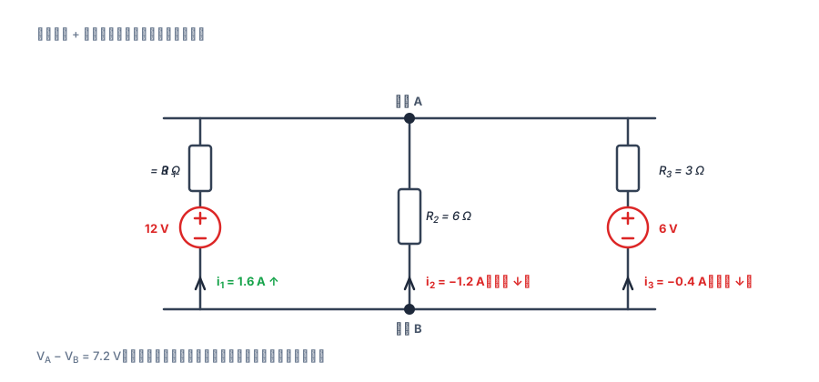
Figure 3: All three currents are first assumed upward. The computed and come out negative, meaning they actually flow downward — not a mistake; the reference directions are opposite.
4 Cautions (each one a pit I've stepped in)
1. You can label reference directions however you like, but stay consistent throughout
For the same wire, labeling "upward" or "downward" are both fine — the computed number just differs by a sign. The negative sign isn't an error; it's information: it tells you the actual direction is opposite to your assumption. What's truly fatal is switching direction midway: if the equation was set up assuming "upward" and you then plug in numbers as if "downward", it's guaranteed wrong.
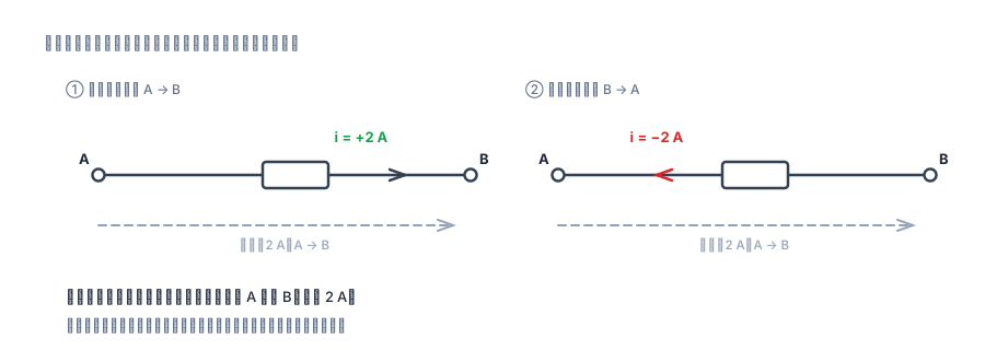
Figure 4: The left and right computations describe the same current. Changing the reference direction doesn't change the answer — it only flips the sign. But never switch midway.
2. A source's "rise/fall" is the easiest thing to get backwards
Going from "−" to "+" is a rise; going from "+" to "−" is a fall. And it depends only on the direction you walk, not on the current direction — the voltage across a voltage source is dictated by the source itself, not by the current. This is the single highest-failure-rate spot in KVL.
3. In loops with changing magnetic flux, KVL can't be applied directly
This is a point almost no introductory textbook emphasizes, but people who build power supplies run into it every day. Once magnetic flux is accounted for, the algebraic sum of voltages around a closed loop is not zero, but:
So KVL cannot be applied as-is in these places:
- Transformers / coupled inductors: primary and secondary each form their own loop, and the magnetic core couples the two sides together;
- The power loop in a switching supply: the small loop formed by the MOSFET, inductor, and diode, where at the moment of commutation is huge and the induced voltage across parasitic inductance makes the oscilloscope waveform look "unconserved";
- Ground loops: when an alternating magnetic field passes between two grounding points, an induced EMF appears on the ground conductor — this is the source of "ground-loop noise".
KVL's standard premise is a lumped-element circuit: every component's dimensions are far smaller than the signal wavelength, the magnetic field is confined inside inductors, and the electric field is confined inside capacitors.
4. At high frequencies and long lines, both iron laws are only approximations
Once a trace length becomes comparable to the wavelength (engineering rule of thumb: beyond ), the distribution of voltage and current along the line can't be ignored, and you must switch to transmission-line equations. KCL/KVL aren't wrong, but the implicit assumption that "everywhere on a node is at the same potential" no longer holds. This is why on a 100 MHz board, two points on the same ground trace can differ by tens of millivolts.
A Little Exercise for Yourself
- Reverse the 6 V source in the trial (+ down) and recompute , , , and . (Hint: the in the right-loop KVL becomes .)
- Write only the KVL of the two meshes plus the KCL of one node, solve for , , , then verify once more with the outer-loop KVL "around the big loop": — check whether it also holds.
- Think about this: why can both the "inflow positive" and "outflow positive" conventions work, yet mixing them yields useless equations like 0 = 0?
Remembering the two iron laws is enough: at a splitter post, in equals out; walk a full loop and you return to where you started. All that's left is labeling directions clearly, substituting signs correctly, and reconciling the power when you're done.